Model Railroad DCC Track Wiring and Diagrams Explained to Avoid Short Circuits
When you approach the subject of implementing Digital Command Control (DCC), there are generally two situations which exist.
First, you may be creating a brand new layout, in which case you can get right to work on making a well-designed and operational layout. Or, you may be converting an existing layout from analog control to DCC.
For most modelers, the first step in the process is generally trying to figure out what DCC feature set, and hence, which DCC system is best for the layout in question.
Feature sets and equipment control features aren’t the only consideration, however. All DCC systems operate the same way, that being to send power and command instructions to the associated decoders via the rails. That one key concept determines how well the DCC layout, in fact, ANY layout, will perform.
How do you Wire DCC Power Districts?
Typical DCC power stations provide up to about five amperes of current to operate the locomotives, with each one requiring from (for HO scale) between a half an amp and an amp.
Numerous articles over the years have established a pretty good system for providing electrical power to a layout. It is generally agreed that a system of feeder busses with drop attachments for power blocks is the preferred method to distribute power around the layout. For smaller DCC layouts, this is still a good method, as is taking the time to solder each rail in the block to its neighbor. A small layout operating two or three locomotives simultaneously would typically only require a single feed bus running the length and breadth of the layout.
What about DCC Short Circuit Protection?
If a short appears across the rails, the power booster is supposed to open an internal circuit breaker and cut off power to the rails to prevent damage. This is pretty effective, but it has the unpleasant side effect of making everything on the layout come to a halt until the short is cleared and the circuit breaker resets. Now, on a small layout, this isn’t too much of a problem. You reach across the layout, re-rail the offending locomotive, and off you go again.
On a large layout, reaching across is usually completely impossible, which is why your layout has access holes and panels (right?). More to the point, such a failure will bring all the other motion on the layout to a screeching halt, idling the other eight or ten operators you have helping you make the railroad work.
How to Prevent Short Circuits
The way we solve this problem is to run individual busses to distant parts of the layout, each with its own lower rating circuit breaker fed by the power booster. This creates a number of parallel powered power districts. When there’s a short in a power district, the circuit breaker controlling that district opens and protects the layout without affecting other parts of the layout.
What about DCC Block Wiring?
If the large layout has existing block control, the power district can replace the control blocks because they are already insulated from each other. This is a good basis for a preliminary design of your power districts but might not necessarily be a good fit for divisions.
For example, a switching yard might have many blocks for analog control of the switching jobs, but with power districts only a single might be required because only one or two switch engines operate in that environment.
Get these two useful e-books and also watch the DCC video here.
Because the blocks are already insulated, they make good starting points. The key feature of power districts is that they also be insulated from each other. If you are creating power districts from scratch, you’ll need to insulate each one. This would involve cutting rail segments and inserting insulating rail joiners to isolate the rails. Each set of rails then needs to be connected to the appropriate power district bus.
How do DCC Control Systems Work?
The whole point of Digital Command Control is to put a throttle to control the train in the hands of the locomotive operator. Every DCC system uses a controller of some kind to command the speed, direction, and headlight condition of the locomotive(s) under its purview. To operate more than one train simultaneously, a throttle is required for each. Every throttle communicates with the command station across some transmission medium. If the throttles are not wirelessly connected in some fashion, the next wiring consideration is for a throttle network. This is usually some form of serial data transmission, often with error control, to allow multiple throttles to be plugged in at once.
A throttle network is similar to a wired home computer network in that a set of wires is run around the exterior edge of the layout with access jacks periodically located along the run. Most vendors have a special jack module available that can be attached to the layout fascia and connected to the throttle bus. The number of jacks and their spacing is arbitrary (within the distance constraints of the transport method employed by the throttle network.)
How does DCC Lighting Wiring Function?
And finally, the last bit of wiring on the layout, which may or may not be DCC controlled is the accessory power. Street lamps, building lights, signaling, motorization and the like require some level of voltage (typically 12 volts DC) to operate. Railroad power packs usually have a fixed 12v output specifically for accessories are not necessarily subject to throttle commands. Accessory busses can be installed right alongside the power feeders as required, with the accessory operating off smaller size wire taps off the main bus just as the rails do. If some form of control of the accessory is arranged via DCC, the DCC commands are usually taken off the rails while the operating power for the accessory can be taken from the accessory bus, leaving the DCC current for the locomotive.
What is Meant by Track Circuit Polarity?

Will Insulated Frogs Prevent Short Circuits?
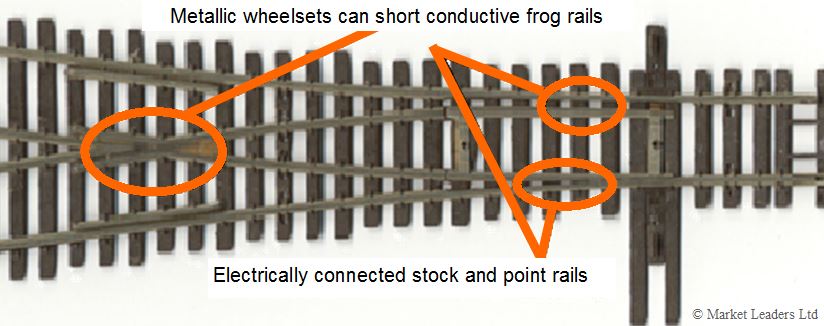
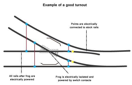
You can see that if a metallic wheelset crosses a “live” or powered frog, there’s an opportunity to short the diverging outside rail to the lined inside rail. This would immediately cause the power district breaker to trip, shutting down the trains! But, if we isolate the frog and switch the polarity to match the turnout direction, the shorting problem is solved as can be seen below. Some track manufacturers have designed their turnouts with insulated frogs to solve this problem. However, with insulated frogs there is a tendency for very short wheelbase locomotives to stall as they go through the insulated points and the driving wheel power pickups are effectively momentarily disconnected from the track. The best solution for this problem is to have a metallic, but isolated frog that is polarity switched when the turnout is thrown, as seen below:

How to Wire for DCC Reversing Loops
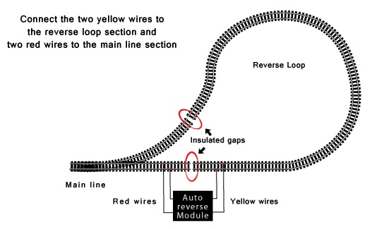
Getting back to our reversing loop, let’s look at the configuration:

The standard, pre-DCC way of handling this was to insulate the loop and provide a double pole-double throw switch to reverse the polarity as the train went round the loop and came out headed in the opposite direction. With DCC, there is an automatic polarity reversing circuit accessory available to handle such a condition. The isolation is still required, but the circuit acts so quickly that the power station has no opportunity to sense the short that happens as the metal locomotive wheels pass over the reversed polarity section. Note that the entry turnout to the loop must still have a frog that will prevent shorts and power district shutdown.
DCC Decoder Programming Options Explained
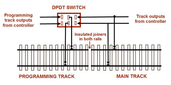
The final DCC electrical consideration is the programming of both mobile and accessory or fixed decoders. While it’s possible to program decoders on the fly on the main line, this isn’t generally good practices – you don’t want to lose control of that expensive locomotive and have it go into the turn at the end of your layout at warp speed. The best thing you can do for your equipment is to create a separate programming track, on which the control station places programming pulses at a much lower current rating to prevent the locomotive motor from turning while you are changing the configuration variables in the decoder.
One convenient method is to create and isolated passing siding which can be switched manually for either line or decoder programming operation. The drawing below shows the wiring of a single ended programming segment. Note that if this segment is on the main line or on a passing siding, insulated joiners must be placed on both ends of the segment, not just one end as shown below:

A Final Word on Wiring for DCC
The one thing we haven’t yet covered is some wiring technical details. As previously mentioned, a typical power booster will supply about 5 amps or less of current. At this power level, #14 or #12 solid hookup wire should be used for the bus runs, with #16 or #18 drop wires to the track connections. Soldering the track drops to the bus wire works fine; be sure to insulate the solder connection with shrink wrap tubing if you do. Otherwise, use the ubiquitous “suitcase” wire splice connector to connect the track drops to the main bus. Just be sure that you use the appropriate size connector for the wire size you are using. A worthwhile investment is a cheap multimeter to help you troubleshoot any issues with the wiring design or installation! $15-20 should get you one that works fine.
